
Physics And Material Science Lab Experiments
We are engaged in manufacturing of complete laboratory experiments measuring instruments for BS and MS laboratories of Physics , Electronics & Electrical Engineering . We are reputed for our quality products and excellent after sales support.
We have been catering to the needs of over 700 institutions in India and abroad since 1979. We, while orienting ourselves to the need of laboratories have been trying our best to develop and introduce progressively more advanced laboratory experiments and general-purpose measuring instruments.
This website highlights some of our manufacturing activities. The technical specifications given here are meant to give an accurate statement of performance of instruments manufactured by us.
- X Ray Diffraction Simulation Experiment
- Zeeman Effect Experiment
- Measurement Of Magneto Resistance In Bismuth
- High Temperature Two Probe Set Up
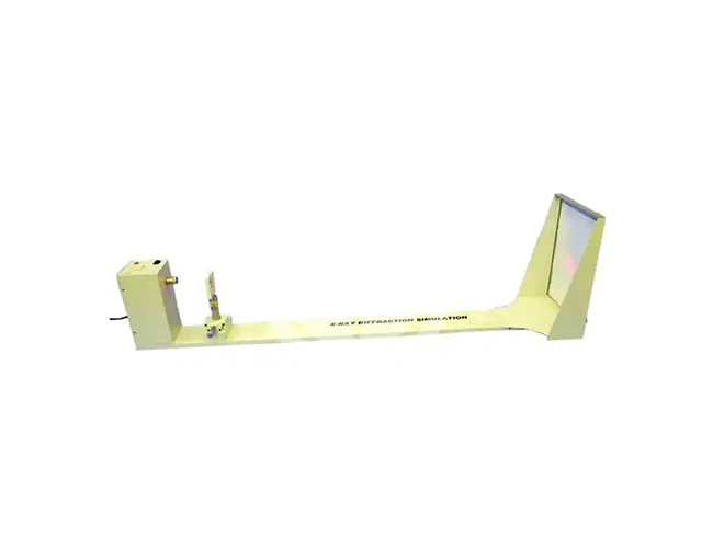
X Ray Diffraction Simulation Experiment
IntroductionRegular arrangement of atoms in molecules and extended solids is very common. In crystalline solids theatoms are arranged in repeating three-dimensional arrays or lattices. Information regarding atomic bonddistances and angles is fundamental to understanding the chemical and physical properties of materials.
Sinceatomic dimensions are of the order of angstroms (10 m), unraveling the relative atomic positions of a solidrequires a physical technique that operates on a similar spatial scale, Diffraction experiments involving X-ray,electron and neutron sources have therefore played a very crucial role in unraveling these structures. Thesignificance of these experiments in science and engineering courses has been recognized. However, the costof the equipment and the hazards associated with these experiments have made them very difficult to beintegrated and included in a teaching laboratory setting.The present set-up overcomes these limitations. An increase in scale by thousands from short wavelengths ofX-rays to the long wavelengths of visible light, and by hundreds of thousands from an array of atoms in acrystal or an extended solid to an array of dots, allows us to replicate the basic features of a structuraldetermination experiment in a teaching laboratory. In place of Bragg diffraction whose results are to be simulated, we use Fraunhofer diffraction. Visible laser lightpasses through an array of scattering centers (dots) on a 35 mm slide. The diffraction pattern is viewed atwhat is effectively infinite distance (a meter or so). This arrangement is capable of illustrating many of theessential features of the standard X-ray experiment.
Mathematically, the equations for Fraunhofer and Braggdiffraction have a similar functional dependence on the interatomic distance, wavelength and the scatteringangle. The symmetry of the diffraction pattern is same as the symmetry of the lattice causing the diffraction.The central piece of the set-up is a slide (transparency) with eight (A-H) different arrangements of scatteringcenters (dots) on different portions of the slide (Figure 3). The examples presented here serve to illustratehow the spacings, symmetries, spot intensities and systematic absences in a diffraction pattern are related tothe lattice from which it is derived. Although these are two-dimensional lattices, they mimic what would beobserved for diffraction from particular three-dimensional structures that are viewed in projectionperpendicular to a face.
SetupA battery operated laser mounted on a stand is put at one end of anoptical bench. The slide is mounted on another stand (Figure 1)which is kept at about 10-20 cm away from the laser such that thelaser light falls normally on the slide. The slide on this stand can bemoved sideways and vertically so that the laser light falls ondifferent portions of the slide. The diffraction pattern is observed ona perspex screen (Figure 2) fixed normal to the laser light at theother end of the optical bench. The whole set-up is put in adarkened room where the experiment is performed.
Aim The basic aim of the experiment is to identify the lattice and to determine its lattice constant.
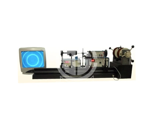
Zeeman Effect Experiment
Introduction
Description of the experimental setup
Experimentental Set-up for Zeeman Experiment
The set-up consists of the following:
- High Resolution Fabry Perot Etalon, FP-01
- Mercury Discharge Tube, MT-01 (Low Pressure Mercury Discharge Tube)
- Power Supply for MT-01, MTPS-01 (H.V. Power Supply for Discharge Tube)
- Narrow Band Interference Filter, IF-01
- Polarizer with lens, PL-01
- Optical Bench: OB-01
- CCD Camera: CCD-01 (High Resolution CCD Camera)
- Telescope with Focussing Lens: FL-01
- Monitor 14”: TV-14
- Electromagnet, EMU-50T
- Constant Current Power Supply, DPS-50
- Digital Gaussmeter, DGM-102
Specifications
| Central Wave Length | 546nm |
|---|---|
| Tmax | 74% |
| HBW | 8nm |
Result
The interference pattern is in the form of circular rings. These are split when the magnetic field is switched on. The amount of splitting depends on the external magnetic field, charge to mass ratio of electron and Lande’s g-factors of the electronic energy levels involved in the transition. These later quantities can be obtained from this experiment.
The result of this unit are within 5% of the standard value.
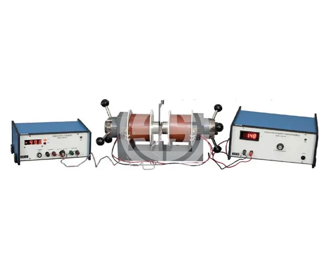
Measurement Of Magneto Resistance In Bismuth
Measurement of Magnetoresistance in Bismuth
It is noticed that the resistance of the sample changes when the magnetic field is turned on. The phenomenon, called magnetoresistance, is due to the fact that the drift velocity of all the carriers is not same. With the magnetic field on; the Hall voltage V = Eyt =|v × H| compensates exactly the Lorentz force for carriers with the average velocity; slower carriers will be over compensated and faster one undercompensated, resulting in trajectories that are not along the applied field. This results in an effective decrease of the mean free path and hence an increase in resistivity.
Here the above referred symbols are defined as: v = drift velocity; E = applied electric field; t = thickness of the crystal; H = Magnetic field
Experimentental Set-Up For Magnetoresistance
- Hall Probe: Bismuth
- Constant Current Source, CCS-01
- Digital Microvoltmeter, DMV-001
- Electromagnet, EMU-75
- Constant Current Power Supply, DPS-175
- Digital Gaussmeter, DGM-102
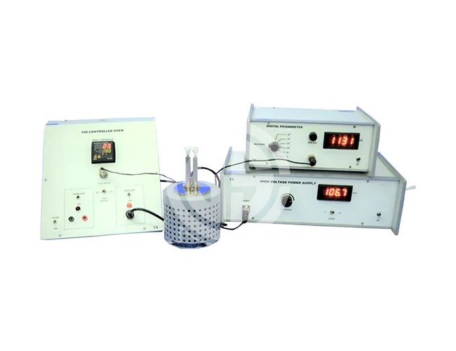
High Temperature Two Probe Set Up
Two Probe Method For Resistivity Measurement of Near Insulators at Different Temperatures (Ambient to 6000C) with computer interfacing facility
Description
Behaviour of resistivity of substarte such as polymer sheets/ films at higher temperatures is an important area of investigation due to their variety of applications. Two Probe Method is one of the standard and most commonly used method for the measurement of resistivity of very high resistivity samples like sheets/films of polymers. The resistivity measurement of such samples is beyond the range of Four Probe Method.
Description of the Experimental Set-Up
- General Physics Laboratory Instruments
- Physics And Material Science Lab
- Physics and Electronics Experimental Setups
- Measurement Of Susceptibility Of Solids
General Physics Laboratory Instruments
Part I/II
| 1a. Digital D.C. Microvoltmeter, Model DMV-001 |
| 1b. Digital D.C. Microvoltmeter, Model DMV-001-C2 (with USB based computer interface and software; also compatible with SES-CAMM) |
| 2a. Digital Nanoammeter, Model DNM-121 |
| 2b. Digital Nanoammeter, Model DNM-121-C2 (with USB based computer interface and software; also compatible with SES-CAMM) |
| 3a. Digital Picoammeter, Model DPM-111 |
| 3b. Digital Picoammeter, Model DPM-111-C2 (with USB based computer interface and software; also compatible with SES-CAMM) |
| 4a. High Voltage Power Supply, Model EHT-11 |
| 4b. High Voltage Power Supply, Model EHT-11-C1 (compatible with SES-CAMM unit, for use in computerised version of our experiments) |
| 5. (a) True RMS A.C. Millivoltmeter, Model ACM-102 (Range:0- 20mV, 0-200mV, 0-2V & 0-20V) |
| (b) True RMS A.C. Millivoltmeter, Model ACM-103 (Same as above but with built in 1KHz oscillator) |
| 6. (i) (a) Electromagnet, Model EMU-75 (pole pieces 75mm flat, 11KG at 10mm air gap) |
| (b) Electromagnet, Model EMU-75T (pole pieces tapered from 75mm to 25mm, 14KG at 10mm air gap) |
| (ii) (a) Constant Current Power Supply, Model DPS-175M (microcontroller based power supply, suitable for long duration operation with EMU-75/ 75T) |
| (b) Constant Current Power Supply, Model DPS-175-C2 (with multiple control/ interface options: Manual; External; USB; SES-CAMM) |
| (c) Constant Current Power Supply (Biopolar), Model DPS-175BP |
| 7. (i) (a) Electromagnet, Model EMU-50V (pole pieces 50mm flat, 7.5KG at 10mm air gap) |
| (b) Electromagnet, Model EMU-50T (pole pieces tapered from 50mm to 25mm, 9KG at 10mm air gap) |
| (ii) (a) Constant Current Power supply, Model DPS-50 |
| (b) Constant Current Power supply, Model DPS-50-C1 (compatible with SES-CAMM unit, for use in computerised version of our experiments) |
| 8. Digital Gaussmeter, Model DGM-102 (Range:0- 2KG & 0-20KG) |
| 9a. Digital Gaussmeter, Model DGM-202 (Range: 0-2KG & 0-20KG; interchangeable Hall Probe) |
| 9b. Digital Gaussmeter, Model DGM-202-C1 (compatible with SES-CAMM unit, for use in computerised version of our experiments) |
| 10. Digital Gaussmeter, Model DGM-103 (Range: 0-2KG, 0-20KG & 0-40KG; with differential mode facility) |
Part II
| 11a. Digital Gaussmeter, Model DGM-204 (Range: 0-0.2KG, 0-2KG , 0-20KG & 0-40KG; interchangeable Hall Probe) |
| 11b. Digital Gaussmeter, Model DGM-204-C2 (with USB based computer interface and software; also compatible with SES-CAMM) |
| 12. Hand Held Gaussmeter, Model DGM-HH-01 |
| 13a. PID Controlled Oven, PID-TZ/ PID-TZ-CT (PID-TZ is general purpose, versatile, high performance PID controlled oven controller coupled with 200°C oven unit (RM-Oven-200) suitable for DFP-RM-200/ TPX-200. PID-TZ-CT is modified to make the above Oven suitable for component testing (CT-Oven- 200) |
| 13b. PID Controlled Oven, PID-TZ-C1 (suitable for TPX-01C, compatible with SES-CAMM unit, for use in computerised version of our experiments) |
| 14. Travelling Microscope, TVM-02 (2-way screw gauge type motion with large dial) |
| 15. Travelling Microscope, TVM-03 (3-way motion – 2 screw gauge type and 1 vernier type) |
| 16. Digital Microscope, DMS-01 (Resolution: 1.3M pixels (1280* 1024 pixels); adjustable magnification 10x~230x; interface: USB 2.0; Built-in 8 switchable Led for illumination; Instant picture snapshots and time-lapse, video recording; Measurement software: measure images by length, angle, area, etc.) |
| 17. Regulated Power Supply, Model PS-12 (±12V & ± 5V) |
| 18. Function Generator, Model: FG-01 (10Hz-2MHz; Square/Sine/ Triangular; Amplitude 0-3V (p-p)) |
Physics And Material Science Lab Experiments Part I
Part I/II/III/IV/V/VI
19. X-Ray Diffraction Simulation Experiment, XDE-01 Complete in all respect |
20. Magnetic Field Measurement Apparatus, MFM-01 Study of magnetic field of a current carrying coil and determination of its radius. And study of superimposition of magnetic fields generated by two coils at different positions Complete in all respect |
21. Study of Dielectric Constant and Curie Temperature of Ferroelectric Ceramics, DEC-01 Complete in all respect |
22. Dielectric Constant of Liquids, Model DCL-01 Dielectric measurements of non conducting liquids. Complete in all respect |
23. Dielectric Measurement Setup, DEC-600 Suitable for temperature upto 600°C, including highly stable PID Controller and Capacitance meter 1pF to 20000μF. |
24. Zeeman Effect Experiment, ZEX-01 Complete in all respect including 14” LCD Flat Panel monitor and CCD Camera |
25. Millikan’s Oil Drop Experiment, MOD-01 (LCD TV) Measurement of electron charge by Millikan’s Experiment. The experiment comes complete with 14” LCD Flat Panel monitor, timer, atomizer etc. The oil droplets can be seen on monitor ensuring convenience & accuracy. |
26. e/m Experiment, EMX-01 Measurement of electron charge to mass ratio, based on Thomson’s method. Complete in all respect |
27. Planck’s Constant by Photoelectric Effect, PC-101 Complete in all respect |
28. Determination of Planck’s Constant by means of LED’s, PCA-01 The method is based on well known expression of diode current for V current with temperature is measured, keeping the V slightly below V0 and material constant h is obtained from V-I characteristics of the diode. Complete in all respect |
29. Frank Hertz Experiment, FH-3001 Complete in all respect, but a oscilloscope will be helpful |
30. Ionisation Potential Set-up, IP-01 Complete in all respect, but a oscilloscope will be helpful |
31. Resistivity of Semiconductors by Four Probe Method at Different Temperatures and Determination of the Band-gap, DFP-02 (Basic Model) Complete in all respect |
32. Resistivity of Semiconductors by Four Probe Method at Different Temperatures and Determination of the Band-gap, DFP-03 (Advance Model) Complete in all respect |
Part II
33. Four Probe set-up for measuring the resistivity of very low to highly resistive samples at temperatures upto 200ºC with PID controlled oven, DFP-RM-200 (Research Model) The set-up consists of the following (i) Four Probe Arrangement with built-in thermocouple sensor, FPA-RM-200 (ii) Standard Samples: Ge, Si and Aluminium (iii) Oven Unit (upto 200C), RM-Oven-200 (iv) High Performance PID Controller, PID-TZ (v) D.C. Microvoltmeter, DMV-001 (vi) Constant Current Source, CCS-01 (Range: 0-20mA & 0-200mA) For low resistivity samples like thin films of metals and alloys (vii) Low Current Source, LCS-02 (Range: 0-2μA, 0-20μA, 0-200μA & 0-2mA) For highly resistive samples Complete in all respect |
34. Four Probe Set-up for Mapping the Resistivity of Large Samples, FP-01 (Mapping Model) The set-up consists of the following (i) Four Probe Arrangement with X-Y movement and vernier scales, FPA-FP-01 (ii) Standard Samples: Ge, Si and Aluminium (iii) D.C. Microvoltmeter, DMV-001 (iv) Constant Current Source, CCS-01 (Range: 0-20mA & 0-200mA) For low resistivity samples like thin films of metals and alloys (v) Low Current Source, LCS-02 (Range: 0-2μA; 0-20μA; 0-200μA; 0-2mA) For highly resistive samples Complete in all respect. |
35. Measurement of Magnetoresistance of Semiconductors, MRX-01 The set-up consists of following units: (Breakup) (i) Four Probe Arrangement, FPA-MRX-01 3200.00 (ii) Sample: Ge Crystal (n-type) _1600.00 (iii) Hall Probe Multipurpose Stand, HPS 900.00 (iv) Magnetoresistance Setup, DMR-01 6800.00 (v) Electromagnet, EMU-50V 25500.00 (vi) Constant Current Power Supply, DPS-50 11500.00 (vii) Digital Gaussmeter, DGM-102 (Optional: DGM-202-Item no. 9) Complete in all respect |
36. Measurement of Magnetoresistance in Bismuth, MRB-11 The set-up consists of following units: (Breakup) (i) Four Probe Arrangement, FPA-MRB-11 (ii) Sample: Bismuth (iii) Hall Probe Multipurpose Stand, HPS (iv) Constant Current Source, Model CCS-01 (v) Digital D.C. Microvoltmeter, Model DMV-001 (vi) Electromagnet, EMU-75 (vii) Constant Current Power Supply, DPS-175M (viii) Digital Gaussmeter, DGM-102 (Optional: DGM-202-Item no. 9) Complete in all respect |

Part III
37a. Two Probe Method for Resistivity Measurement of Insulators, TPX-200 (upto 1013W.cm.) at Different Temperatures The set-up consists of the following (i) Two Probe Arrangement with built-in thermocouple sensor, TPA-TPX-200 (ii) Test Sample: 50M resistance (not for experiment) (iii) Oven Unit (upto 200°C), RM-Oven-200 (iv) High Performance PID Controller, PID-TZ (v) High Voltage Power Supply, EHT-11 (vi) Digital Picoammeter, DPM-111 Complete in all respect. |
37b. Two Probe Method for Resistivity Measurement of Insulators,TPX-200C (upto 1013W.cm.) at Different Temperatures with USB based computer interface The set-up consists of the following (i) Two Probe Arrangement with built-in thermocouple sensor, TPA-TPX-200 (ii) Test Sample: 50M resistance (not for experiment) (iii) Oven Unit (upto 200°C), RM-Oven-200 (iv) High Performance PID Controller with computer interface, PID-TZ-C1 (v) High Voltage Power Supply, EHT-11C (vi) Digital Picoammeter, DPM-111C (vii) Computer Aided Measurement Module, SES CAMM, complete with suitable software Complete in all respect. |
37c. High Temperature Two Probe Set-up, TPX-600 (Suitable for temperature upto 600°C, including highly stable PID Controller, 1500V EHT Power Supply and high resolution Picoammeter) The set-up consists of the following (i) Two Probe Arrangement with built-in thermocouple sensor, TPA-TPX-600 (ii) Test Sample: 50M resistance (not for experiment) (iii) Oven Unit (upto 600°C), RM-Oven-600 (iv) High Performance PID Controller, PID-TZ (v) High Voltage Power Supply, EHT-11 (vi) Digital Picoammeter, DPM-111 Complete in all respect. |
37d. High Temperature Two Probe Set-up, TPX-600C with USB based computer interface facility (Suitable for temperature upto 600°C, including highly stable PID Controller, 1500V EHT Power Supply and high resolution Picoammeter) The set-up consists of the following (i) Two Probe Arrangement with built-in thermocouple sensor, TPA-TPX-600 (ii) Test Sample: 50M resistance (not for experiment) (iii) Oven Unit (upto 600°C), RM-Oven-600 (iv) High Performance PID Controller with computer interface, PID-TZ-C1 (v) High Voltage Power Supply, EHT-11C (vi) Digital Picoammeter, DPM-111C (vii) Computer Aided Measurement Module, SES CAMM, complete with suitable software Complete in all respect. |
38. Electron Spin Resonance Spectrometer, ESR-105 Complete in all respect, except a oscilloscope |
39. NMR Experiment, NMR-01 Complete in all respect, except a oscilloscope |
Part IV
40. Study of Thermoluminescence of F-centres in Alkali Halide Crystals, TLX-02 63700.00 The set-up consists of following units: (Breakup) (a) Experimental set-up for creating the Thermoluminescence, TL-02 (Oven with power supply, digital thermometer, samples, black box etc.) |
(b) For Measuring of Luminescence Intensity 1. Photomultiplier Tube-931A/ R11558 2. PMT Housing with biasing circuit 3. EHT Power Supply, Model EHT-11 4. Digital Nanoammeter, Model DNM-121 Complete in all respect, except XRF/ XRD facility, which is required to irradiate the sample. Thermoluniscence Irradiation Unit, TEI-01 can also be used for sample preparation. |
41. Thermoluminescence Irradiation Unit, TEI-02 (Irradiation unit suitable for irradiating alkali halide samples for thermoluniscence experiment) Complete in all respect including vacuum pump and HV electric field generator |
42. Hall Effect Experiment, HEX-21 0 The set-up consists of following units: (i) (a) Hall Probe (Ge Crystal – n type) (b) Hall Probe (Ge Crystal – p type) (ii) Hall Probe Multipurpose Stand, HPS (iii) Hall Effect Set-Up, Model DHE-21 (iv) Electromagnet, Model EMU-50V (Optional: EMU-75-Item no. 6ia) (v) Constant Current Power Supply, DPS-50 (Optional: DPS-175M -Item no. 6iia) (vi) Digital Gaussmeter, DGM-102 (Optional: DGM-202-Item no. 9a) Complete in all respect |
43. Hall Effect Experiment, HEX-21C The set-up consists of following units: (Breakup) (i) (a) Hall Probe (Ge Crystal – n type) (b) Hall Probe (Ge Crystal – p type) (ii) Hall Probe Multipurpose Stand, HPS (iii) Hall Effect Set-Up, Model DHE-21C (iv) Electromagnet, Model EMU-50V (Optional: EMU-75-Item no. 6ia) (v) Constant Current Power Supply, DPS-50C (Optional: DPS-175C -Item no. 6iib) (vi) Digital Gaussmeter, DGM-202C (Optional: DGM-204C-Item no.11b) (vii) Computer Aided Measurement Module, SES CAMM-2, complete with suitable software Complete in all respect |
44. Hall Effect Experiment, HEX-Research The set-up consists of following units: (Breakup) (i) (a) Hall Probe (Ge Crystal – n type) (b) Hall Probe (Ge Crystal – p type) (c) Hall Probe Mount (For 10mmx10mm sample) (c) Hall Probe Mount (For 5mmx50mm sample) (ii) Hall Probe Multipurpose Stand, HPS – 2pcs (iii) Digital Microvoltmeter, DMV-001 (iv) Constant Current Power Supply, CCS-01 (iv) Electromagnet, Model EMU-75T (v) Constant Current Power Supply, DPS-175M (vi) Digital Gaussmeter, DGM-202 |
Part V
45. Hall Effect in Bismuth, HEB-11 The set-up consists of following units: (i) Hall Probe : Bismuth (ii) Multipurpose Stand (iii) Digital Microvoltmeter, DMV-001 (iv) Constant Current Power Supply, CCS-01 (iv) Electromagnet, Model EMU-75 (v) Constant Current Power Supply, DPS-175M (vi) Digital Gaussmeter, DGM-202 Complete in all respect |
46. Hall Effect in Metals, HEM-01 The set-up consists of following units: (i) (a) Hall Probe (Silver-Ag) (b) Hall Probe (Tungsten-W) (ii) Multipurpose Stand (iii) High Current Power Supply, PS-20 (iv) Digital D.C. Microvoltmeter, DMV-001 (v) Electromagnet, Model EMU-75T (vi) Constant Current Power Supply, DPS-175M (vii) Digital Gaussmeter, DGM-202 Complete in all respect |
47. Dependence of Hall Coefficient on Temperature, HEX-22 The set-up consists of following units: (i) Hall Effect Setup, Model: DHE-22 (ii) Hall Probe (Ge : p-type) with a small oven and a Thermocouple (iii) Hall Probe Multipurpose Stand, HPS (iv) Electromagnet, Model EMU-50V (Optional: EMU-75-Item no. 6ia) (v) Constant Current Power Supply, DPS-50 (Optional: DPS-175M -Item no. 6iia) (vi) Digital Gaussmeter, DGM-102 (Optional: DGM-202-Item no. 9a) Complete in all respect |
48. Apparatus for the Measurement of Susceptibility of Paramagnetic Solution by Quinck’s Tube Method, QTX-01 The set-up consists of following units: (i) Quinck’s tube (ii) Q-Tube multipurpose Stand, QTS (iii) Sample : MnSO4.H2O (iv) Travelling Microscope, TVM-02 (Optional: Digital Microscope – Item no. 15) (v) Electromagnet, Model EMU-50T (Optional: EMU-75T-Item no. 6ib) (vi) Constant Current Power Supply, DPS-50 (Optional: DPS-175M -Item no. 6iia) (vii) Digital Gaussmeter, DGM-102 (Optional: DGM-202-Item no. 9) Complete in all respect, except chemical balance. |
49a Apparatus for the Measurement of Susceptibility of Solids by Gouy’s Method, GMX-01 (with EMU-75 & DPS-175M)* (Suitable for different variety of samples) |
Part VI
49b Apparatus for the Measurement of Susceptibility of Solids by Gouy’s Method, GMX-01 (with EMU-50 & DPS-50) (Suitable for classroom experiment) The set-up consists of following units: (i) Scientific Balance, KSB-07 (with weight box) (ii) Al. Samples and Glass Tube for powder samples (iii) Gouy’s Balance Stand (iv) Electromagnet, Model EMU-75T * (with 49a) (v) Constant Current Power Supply, DPS-175M * (with 49a) (vi) Digital Gaussmeter, DGM-102 (Optional: DGM-202-Item no. 9a) (iv) Electromagnet, Model EMU-50T (with 49b) (v) Constant Current Power Supply, DPS-50 (with 49b) Complete in all respect. |
49c Apparatus for the Measurement of Susceptibility of Solids by Gouy’s Method, GMX-02 (with EMU-75T & DPS-175)* |
49d Apparatus for the Measurement of Susceptibility of Solids by Gouy’s Method, GMX-02 (with EMU-50T & DPS-50) (Suitable for different variety of samples) The set-up consists of following units: (Breakup) (i) Digital Balance, ATY224 SHIMADZU (ii) Al. Samples and Glass Tube for powder samples (iii) GMX-02 Trolley (iv) Electromagnet, Model EMU-75T* (with 49c) (v) Constant Current Power Supply, DPS-175M* (with 49c) (vi) Digital Gaussmeter, DGM-202 (iv) Electromagnet, Model EMU-50T (with 49d) (v) Constant Current Power Supply, DPS-50 (with 49d) Complete in all respect. |
50a. Magnetic Hysteresis Loop Tracer, HLT-111 Complete in all respect, except a oscilloscope. |
50b. Magnetic Hysteresis Loop Tracer, HLT-111C (USB based computer interface through SES CAMM. Complete in all respect with SES-CAMM unit and software, except a oscilloscope) |
51. Study of the energy band-gap and diffusion potential of P-N Junctions, PN-01 Complete in all respect, except a oscilloscope. |
52. Study of Diode Characteristics, SDC-02 Study of Si, Ge, LED & Zener diodes. Direct measurement of Voltage & Current (100nA to 20mA) and provision for direct display of diode characteristics on oscilloscope Complete in all respect, except a Oscilloscope |
Physics and Electronics Experimental Setups
53. Study of a Transistor Amplifier (RC Coupled) Cum-Feed Back Amplifier, Model: RC-01 Accessories required : (i) Function Generator (Item no. 18) (ii) True RMS A.C. Millivoltmeter (Item no. 5a) |
54. Study of Multivibrators, Model: MV-01 Complete in all respect, except a oscilloscope |
55. Study of Characteristics of Semiconductors Diodes Si, Ge, Zener & LED, Model: D-1 Complete in all respect. |
56. Study of Hybrid Parameters of Transistors, Model: HP-01 Accessories required : (i) True RMS A.C. Millivoltmeter with 1KHz. Oscillator (Item no. 5b) |
57. Study of a Solid State Power Supply, Model: SSPS-02 Complete in all respect including electronic load and voltmeter/ ammeter |
58. Study of Modulation & Demodulation with Built-in Carrier Frequency (Solid State), Model: MD-01 Accessories required : (i) Function Generator (Item no. 18), (ii) Oscilloscope (N.M.) |
59. Study of a Basic Operational Amplifier Type-74l, Model: 741-01 Complete in all respect |
60. Study of Op Amp 74l Applications, Model: 741-03 Complete in all respect, including signal generator, regulated power supplies, multirange digital voltmeter and patch chords, except a oscilloscope. |
61. Study of Astable & Monostable Multivibrators using Timer IC, Model: 555 Complete in all respect, including power supply and a trigger, except a oscilloscope. |
62. Study of an Integrated Circuit Regulator, Model: 723 Complete in all respect, including unregulated power supply, a voltmeter, an ammeter, variable load resistance and patch chords. |
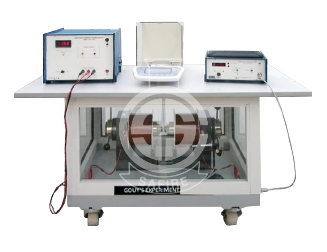
Measurement Of Susceptibility Of Solids By Gouy's Method
Apparatus for Measurement of Susceptibility of Paramagnetic Solids by Gouy’s Method
The set up consists of the following:
a) Digital Balance, ATY224 SHIMADZU JAPAN
| Capacity | 2200 gms |
| Readability | 0.0001 gms |
| Repeatability | ± 0.1 mg |
| Linearity | ± 0.2 mg |
| Pan Size | ± 90mm |
| Standard | Bidirectional RS-232 interface |
| Special Feature | Weight below hook for GMX-02 |
b) Sample in the form of a long rod
c) Electromagnet, Model EMU-75T
| Pole Peice | 75mm tappered to 25mm |
| Mag. Field | 20KG at 6mm airgap |
| Energising Coils | Two of approx. 13Weach |
| Power | 0-90Vdc, 3A, for coils in series 0-45Vdc, 6A, for coils in parallel |
d) Constant Current Power Supply, Model : DPS-175
e) Digital Gaussmeter, Model : DGM-202
f) GMX-02 Trolley, Model, GMX-TR2
The experiment is complete in all respect
Get in touch with us right now…
Our friendly customer service representatives are committed to answering all your questions and meeting you in person, if need be. We would love to hear from you! Please fill out the form to assist you.